
Many signal integrity and communication issues with RS-485 networks stem from terminations, either from a lack of termination or improper termination. In this installment of the RS-485 basics series, I’ll talk about when you can get away without terminating your RS-485 network, and if you need termination, how to use standard (parallel) terminations and alternating current (AC) termination networks.
As I discussed in the last installment of this series, an RS-485 transceiver’s driver must be able to drive 1.5V across 32 unit loads and two 120Ω terminations. I didn’t mention it in the post, but the 120Ω value for termination resistors stems from what is known as the differential-mode characteristic impedance of the twisted-pair bus wires. Simply put, the wire gauge, insulation type and thickness, and number of twists per unit length all contribute to an impedance that high-speed data signals “see.” This impedance is denoted in ohms and typically ranges from 100Ω to 150Ω for twisted-pair cables. The writers of the RS-485 standard choose 120Ω as the nominal characteristic impedance; therefore, to match this impedance the termination resistors also have a default value of 120Ω.
Why termination networks exist
Matching the characteristic impedance of the cabling to the termination network enables the receiver on the end of the bus to see the maximum signal power. By leaving a transmission line unterminated, or terminated with some value unequal to the impedance of the cable, you are introducing a mismatch that creates reflections at the ends of the network. A reflection is where some of the energy of the signal literally returns back up the line, which can then constructively or destructively interfere with the next bits propagating down the bus. A destructive example is if the reflected signal which bounces back is out of phase with the incoming signal, resulting in the receiver seeing a smaller incoming signal. If the mismatch is large enough, the energy reflected back can cause subsequent bits to be misinterpreted and incorrectly decoded by the receiver.
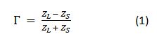
Equation 1 shows that for the reflection coefficient, to approach zero, the input impedance, ZL, needs to match the source impedance, ZS. If there is a large discrepancy in load and source impedance, almost the entire signal can reflect.
As you can see, for optimal signal integrity, it is always best to match the AC line impedance with a termination of equal value. Why wouldn’t all designers want to do this? Because adding termination networks adds cost to the overall system, and these termination networks also add a parallel load to the drivers, causing larger steady-state load currents. In power-sensitive applications where lowering power consumption is critical (such as in battery-powered applications), one option to save power is to leave the bus unterminated. Let’s discuss when removing termination is a viable option.
Networks that do not need termination
One situation in which you don’t need termination networks is when the two-way loop time of the network is much greater than a single bit time (~<0.1×two-way loop delay). In such scenarios, the reflections will lose energy each time they reach an end of the network.
As you can see from Figure 1, the amplitude of the reflections will continue to decay each time the signal reflects at the end of the cable. Figure 1 shows three round trips for the signal and a total of six reflections.
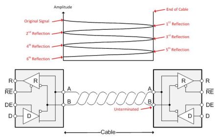
Figure 1: Amplitude of reflection decay each time a reflection occurs
Estimating that the unterminated end of the bus has a 96kΩ input impedance (a one-eighth unit load), and the source impedance of the driver is 60Ω, the signal reflections would decay according to the calculations listed in Table 1.

Table 1: Example signal-decay calculations
As Table 1 shows, by the time the signal reflects for the sixth time, it has decayed to under 4% of its original magnitude. After this point it is safe to say that the reflections are no longer capable of causing signal-integrity issues. Since the sample point of a bit typically occurs between 50-75% of the way through the bit, you would want to make sure that these three round-trip delays occur before the sample point.
Networks that need termination
For applications where the bit time is not substantially longer than the loop time of the cable, termination is crucial for minimizing reflections. The most basic termination networks, which are known as standard termination or parallel termination networks, consist of a single resistor (Figure 2).
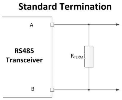
Figure 2: Standard termination network
For standard termination, you would match the termination resistor value with the differential-mode characteristic impedance of the cabling on both ends of the network. This ensures the proper termination of signals traveling in both directions on the bus. As I mentioned before, the major drawback for this type of termination scheme is that whenever the driver is active, the resistors are placing a direct current (DC) load on the driver.
Using AC terminations helps alleviate this power dissipation without having as long of a bit-time requirement with respect to bus length. Figure 3 shows an AC termination scheme.
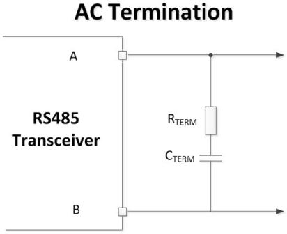
Figure 3: AC termination network
Since current typically flows from one side of an RS-485 driver through the termination network, then through the other side of the driver, by placing a series capacitor the steady state current goes to zero. The two caveats of this type of termination are that it requires one extra component on each termination network, and the series resistor and capacitor introduce a resistor-capacitor (RC) delay. The RC time constant will slow the rising and falling edge of the differential signal and limit the maximum data rate of the network.
Table 2 summarizes the three termination scenarios.
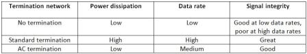
Table 2: Summary of termination techniques
For optimal signal integrity, it is always best to match the differential-mode characteristic impedance of the cable with a termination of equal impedance. But if you take the proper steps, it is also possible to successfully implement AC terminations or avoid termination altogether.
As always, log in and leave a comment if there are any RS-485 topics you would like to hear more about.
联系客服

