
In the last installment of this series, I discussed when you need terminations in an RS-485 network and how to implement both standard and AC termination schemes. In this installment, I will explore two common ways to handle idle bus conditions so that there is a guaranteed logical state on the bus.
Because RS-485 is a multipoint topology network and is not able to handle contention, there will be times where all RS-485 transceivers on the bus are presenting high impedance and no logical state is being actively driven. Most commonly, this will occur between when one node finishes transmitting a message and the next node begins transmitting a message. During these times, the bus will have a 0V differential signal due to the installed termination resistors. Per the Electronic Industries Alliance (EIA)-485 standard, the input thresholds of an RS-485 receiver are logically high for differential voltages ≥+200mV and logically low for differential voltages ≤-200mV. This means that there is a 400-mV indeterminate state for differential input voltages, as shown in Figure 1.
Figure 1: RS-485 receiver input thresholds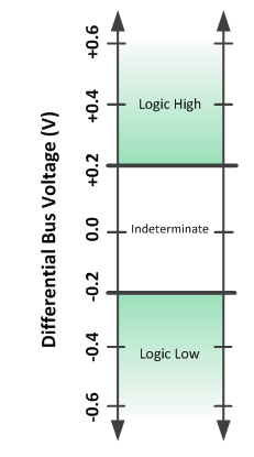
The two most common ways of handling this indeterminate state are to either select receivers that have built-in fail-safe input thresholds or use additional external resistors to create an external bias on the idle bus. Both methods ensure a logical high state on the bus, which corresponds to a positive differential voltage.
If you look back at the RS-485 basics blog post on receivers, I discussed how to achieve a built-in fail-safe input bias. The quick explanation is that an internal bias current created inside the attenuation network then creates a voltage difference at the input of the receiver’s comparator. The benefit of this solution is that it has no effect on the loading of all of the transceivers on the network. The caveat is that every single node on the network will need to have this feature built-in. For existing installations, or installations using previously designed modules that may be hard to update, this may not be a realistic option.
The second way to handle idle bus conditions is to use two external resistors: one from the A terminal to VCC and the other from B terminal to ground. See the two red resistors in Figure 2.
Figure 2: Fail-safe resistor placement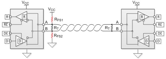
As you can see with RFS1, the two parallel termination resistors (RT) and (RFS2) create a simple voltage divider circuit. You only need to install these resistors in one node on the entire network, typically on the master node. Additionally, RFS1 and RFS2 are set equal to each other so that the common mode is balanced between VCC and ground.
Equation 1 is the simplest way to calculate the value of these fail-safe resistors. Take the minimum input voltage that results in a known state (+200mV), the equivalent termination resistors in parallel (60Ω) and the minimum VCC for the node that will have the fail-safe resistors populated (let’s use 4.5V) and solve the simple voltage-divider equation:

Substituting VFS = 200mV, Req = 60Ω and setting RFS1 + RFS2 = 2*RFS (since we are setting them equal to each other), you get:
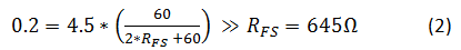
As you can see, the benefit to this solution is that it only takes two resistors to accomplish, and it works for all nodes on a network. The caveat is that the two 645Ω resistors create a common-mode load. If you recall from a previous post in this series on unit loads, each RS-485 driver is required to handle a 375Ω common-mode load (32 unit loads in parallel), as shown in Figure 3.
Figure 3: 32 unit loads in parallel presenting a common-mode load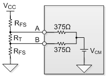
The issue is that the fail-safe resistors alone are presenting a common-mode load of 645Ω. It is now important to calculate what additional common-mode load may be present in parallel before a common-mode loading of 375Ω is present:
Since each unit load can be approximated by a 12kΩ common-mode load, all you have to do is calculate the maximum number of unit loads in parallel that you can have before presenting a common-mode load of less than 896Ω:

This means that the fail-safe resistors place a common-mode loading equivalent to 18.6 (32-13.4) unit loads, thereby drastically reducing the total number of allowable nodes on the network. As you can see, both methods of handling idle bus conditions have pros and cons, so it will be up to you to decide which method works best for your application.
As always, log in and leave a comment or visit the TI E2E™ Community Industrial Interface forum if there are any RS-485 topics you would like to hear more about. You can search our complete RS-485 portfolio here.
Additional resources
联系客服

