Basic function principles
The KL3356 Analog Input Terminal is used to acquire the supply voltage to a load cell as a reference voltage, and simultaneously the differential voltage that is proportional to the force acting on the cell. The reference and the differential voltages are measured alternately by the same converter. The quotient of the differential and the reference voltages corresponds to the force that is acting on the load cell. Deviations in the analog input stages (temperature drift, long-term drift etc.) are checked by regular calibration, and compensated to bring the measurement within the permitted tolerance range.
Strain gauge measuring signal
The strain gauge measuring signal is acquired at fixed intervals with a resolution of 16 bits (+ sign). This value is saved as a data word, without sign, in register
R2. The sign is represented in bit
SW.0 of the status word.
The length of the sampling interval is directly determined by the filter constant in register
R37.
Strain gauge reference signal
The strain gauge reference signal is also acquired with a resolution of 16 bits (+ sign) at longer intervals. This value is saved as a data word, without sign, in register
R3. The sign is represented in bit
SW.1 of the status word.
The length of the sampling interval is defined, in multiples of 100 ms, in register
R39.
Calculating the weight
Every time the analog signal is acquired, the weight that it indicates is calculated. This is composed of the ratio between the measuring signal and the reference signal, and of a number of calibrations:
YR = (UDiff / URef) x (Emax / Cn) x 1000 / 500
(1.0)
Calculation of the raw weight value
YS = YR x AS
(1.1)
Scale factor
YH = YS x AH + BH
(1.2)
Manufacturer scaling
YOUT = YH x AA + BA
(1.3.0)
User scaling (if
R32.10=0bin)
YOUT = (YH + BA) x AA
(1.3.1)
User calibration (if
R32.10=1bin)
Key
Name
Name
Unit
Register
UDiff
Measuring signal from the load cell
[1]
R2URef
Reference signal from the load cell
[1]
R3Emax
Nominal weight of the load cell
[1 kg]
R35Cn
Nominal parameter of the load cell
[1 mV / V]
R36AS
Scale factor (can be activated via bit
R32.8 of the feature register)
[1]
R38BH
Offset of the manufacturer scaling (can be activated via bit
R32.1 of the feature register)
[1]
R19AH
Gain of the manufacturer scaling (can be activated via bit
R32.1 of the feature register)
[1]
R20BA
Offset of the user's scaling (can be activated via bit
R32.0 of the feature register)
[1]
R33AA
Gain of the user's scaling (can be activated via bit
R32.0 of the feature register)
[1]
R34The factor of 1000 in
formula 1.0 results from normalizing the units of the nominal weight [kg] and the nominal parameter [mV/V]. The factor 1/500 is specified through a voltage divider. The result is written into the terminal's process image with a resolution of 16 bits (+ sign). This value is saved as a data word, without sign, in register
R1. The sign is represented in bit
SB1.0 of the status byte.
Operation modes
The KL3356 provides different operation modes:
Operation mode
Comment
Normal operation
Measuring the force acting on the load cell
Zero calibration
The DC voltage potential at the inputs to the operational amplifier corresponds to that of normal operation. The differential voltage at the two operational amplifier inputs is 0 mV (determination of the zero points).
Final calibration
The DC voltage potential at the inputs to the operational amplifier corresponds to that of normal operation. The divided cell supply voltage (R114, R115, R151) is applied as a differential signal to both the operational amplifier inputs (determination of the amplification factors).
Null-test (0 V)
The DC voltage potential at the operational amplifier inputs is set to 0 V. The differential voltage at the two operational amplifier inputs is 0 mV (first stage in establishing the Common Mode Rejection of the operational amplifiers).
Null-test (2.5 V)
The DC voltage potential at the operational amplifier inputs is set to 2.5 V. The differential voltage at the two operational amplifier inputs is 0 mV (second stage in establishing the Common Mode Rejection of the operational amplifiers).
Reference test
The DC voltage potential at the inputs to the operational amplifier corresponds to that of half the reference voltage. The divided reference voltage (R114, R115, R151) is applied as a differential signal to the two operational amplifier inputs (measurement of the reference voltage).
Switch settings
The various operation modes are selected by means of internal switches:
▪
Switch SW1 is switched by bit
R32.7 of the feature register, and is to be closed for all calibration processes:
- R32.7 = 0: SW1 open
- R32.7 = 1: SW1 closed
▪
If manual calibration mode is enabled in the command register
R7 you can control switches SW2 to SW8 by means of the output data word
RegOUT.
Operation mode
RegOUT
Switch settings
SW1
SW2
SW3
SW4
SW5
SW6
SW7
SW8
Normal operation
0dec
0 / 1
1
1
0
1
0
1
0
Zero calibration
1dec
0 / 1
0
1
1
0
0
0
0
Final calibration
2dec
0 / 1
0
0
1
1
0
1
0
Null-test (0 V)
3dec
0 / 1
0
0
1
0
0
0
1
Null-test (2.5 V)
4dec
0 / 1
0
0
1
0
1
0
0
Reference test
5dec
0 / 1
0
0
1
0
1
0
1
Key
0: switch not connected
1: Switch connected
Calibrating the measuring amplifiers
The measuring amplifiers are periodically subjected to examination and calibration. For this purpose a total of eight analog switches are provided in order to be able to connect the various calibration signals. It is important for this process that the entire signal path, including all passive components, is examined at every phase of the calibration. Only the interference suppression elements (L/C combination) and the analog switches themselves cannot be examined.
The calibration interval is set in register
R40 in steps of 100 ms. The test interval is specified in register
R41 as a multiple of the calibration interval.
▪
In the first phase of the calibration, an input voltage of 0 mV is applied to both analog inputs (
zero calibration). The zero points of both analog input stages can be determined in this way. This involves a system offset calibration of the A/D converter. In this measurement, both the respective absolute values and the mutual deviation of the channels are of interest.
▪
An input voltage of approx. 24 mV is applied to both analog inputs in the second phase of the calibration (
final calibration). This is derived from the power supply to the load cell. At this point the absolute value of the measurements is no longer an interest, only any possible deviation of the values for the two analog inputs. The gain of the first channel is adjusted here to match that of the second channel. The important point is that the calibrations are carried out using the same DC voltage potential at the inputs to the operational amplifiers, as in a normal measuring operation.
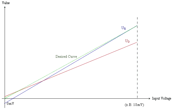
Calibrating the input stages at both working points (the zero point and the final value) allows the straight lines of the two measuring channels to be adjusted to one another so that they are congruent.
Characteristic curves for calibration
If the terminal is carrying out a calibration, bit
R0.2 is set in register 0 (the status word).
Testing the measuring amplifiers
In order to be able also to test the function of the analog input circuits and the source of the reference voltage, it is also possible, in addition to the calibration described, to connect the internal reference voltage signal of 2.5 V as the input signal. For this purpose, before measuring the reference voltage itself, a difference voltage signal of 0 V with a DC voltage potential of 0 V is applied. Measurement of the 0 V differential signal combined with a DC voltage potential of 2.5 V is then carried out. With the aid of the measured values resulting from this, the CommonMode effect of the two input stages at an input voltage of 1.25 V can be calculated, and can be taken into account in the subsequent measurement of the reference voltage. When measuring the source of the reference voltage, both operational amplifiers must deliver the same measuring signal, in addition to which it must also be possible to predict the value to within a very tight tolerance. If this tolerance is exceeded, the situation is classified as a hardware defect, and is indicated in bit
SW.8 of the status word.
If the terminal is carrying out a test, bit
R0.2 is set in register 0 (the status word).
Initiating the calibration or test
The calibration and test procedures are executed by the terminal automatically after the times specified in
registers R39 to R41have elapsed. Bit
CB1.1 of the control byte can be used to block the automatic calibration (this command is acknowledged in bit
SB1.1 of the status byte) in order to prevent calibration from taking place during a time-critical measurement. So that calibration is not completely suppressed in this way, the KL3356 monitors the calibration cycle, and autonomously starts a forced calibration if the block remains in place for too long. The time after which the terminal will carry out this forced calibration is specified in register
R44 as a multiple of register
R40. At each measurement, the reference voltage is compared with the contents of register
R45 (in units of 1 mV). If it is found to be below this limit, bit
R0.14 is set.
If it is necessary to initiate a test manually, it is started by bit
CB1.0 of the control byte. Completion of a test is signaled by bit
R0.4 in register R0 (the status word). The result of the last test is represented by a difference in the two analog inputs, and can be placed into registers
R1 to
R3 and
R5 by bit
CB1.2 of the control byte. Valid calibration data is present if bit
R0.5 in register 0 (status word) is set to 1bin. Register write protection can be set by bit
CB1.3 to prevent the calibration data from being modified (this is acknowledged by bit
SB1.3)
Manual operation
▪
Under some circumstances it may be necessary to observe the values from the A/D converter directly. For this purpose the terminal can be switched to manual operation. To do this, first enter the user code word (1235hex) in the code word register
R31 to clear write protection from the user register.
▪
Then enter the value 0401hex into the command register (
R7) to switch to manual operation. If you enter the value 0 into register R7, manual operation is halted once more.
In manual operation, the value in the
RegOUT output word returns the setting of the input switches (see table of
Switch settings). You can use bit
CB1.1 of the control byte to switch between OP1 and OP2 (CB1.1=0bin: OP1; CB1.1 =1bin: OP2).
A forced calibration is automatically carried out as soon as you return the terminal to normal operation again.
Error diagnosis
The KL3356 offers internal error diagnosis. The upper 8 bits of register
R0 (the status word) indicate errors that have occurred.
So that the user does not have to keep reading register R0, any change in the error bits (if, for instance, a new error has occurred or if an existing error has been cleared) is indicated in bit
SB1.6 of status byte 1. All errors that have occurred are temporarily stored, and are not cleared by the terminal on its own account. By setting bit
CB1.6 in control byte 1 you can reset error bit
SB1.6.
Measured value stabilization
During self-calibration, various signals are switched internally as described above. After the self-calibration has been completed, depending on the setting of R32.9 (stabilization of the calibration), the following behavior occurs:
- Stabilization active (R32.9 = 1): the terminal waits until the signal has stabilized as specified in register R47/R48 and only then outputs measured values to the bus again - this extends the pause until the terminal measures again and can cause the terminal to wait until measurement in the event of an unstable input signal.
- Stabilization inactive (R32.9 = 0): the terminal immediately switches the measuring signal back to the bus - this can lead to a swing-in process being observed in the measured value over several cycles.